
SunCorGraph-I Coronagraph
Construction of a solar coronagrpah of the Lyot classic type - 2023
In this article, we explain the construction of our Lyot-type solar coronagraph, which we have named SunCorGraph-I. We will not explain the principles of the classic Lyot coronagraph, as there is a wealth of information available in books, articles, and on specialized websites. Figure 1 shows SunCorGraph-I, with the occulting disc uncovered. The reflection of the sun light on the occulting cone can be seen as a bright yellow light emerging from it.
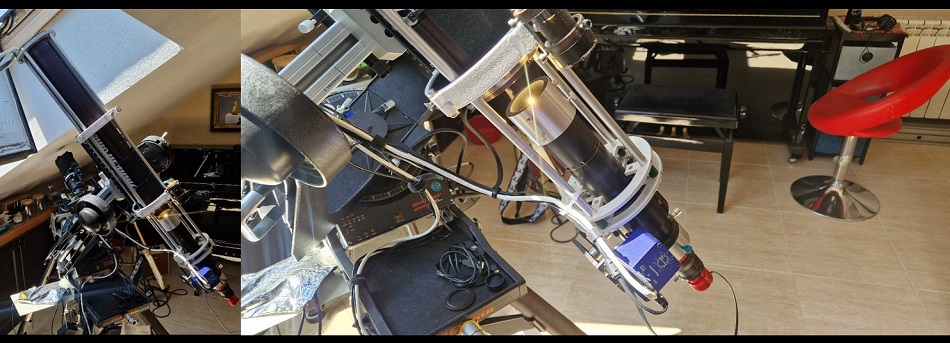
Figure 1.- Pictures of SunCorGraph-I. On the left, a global view of the device can be seen, where the occulting cone is uncovered, allowing to see the dispersion of the sun light on it. On the right, a close-up picture with the occulting.
In Figure 2, a diagram of the classical Lyot coronagraph is depicted. The telescope`s main lens is indicated as O1, the cone as S, the field lens as O2, and the relay (telecentric) lens group as O3 and O4. The Lyot stop is labeled D, and the filter between O3 and O4 is F. O4 is the responsible of forming the final image at the camera sensor plane.
In the explanations below, the objective lens will be referred as the main lens, while the rest of the elements from the occulting cone S to the O4 lens will be referred as the Lyot assembly. The Lyot assembly is mounted on a tube that can be easely detached from the telescope in order to change the configuration of lenses.
The calculation of the different positions of lenses and the Lyot stop are calculated by using an excel sheet that we have developed for this purpose. The entries in the Excel sheet are the main focal length, the focal lengths of O2,O3 and O4, the position of the cone with respect to the field lens (X in figure 2), and the distance between O3 and O4. From this, position of O1, O2, O3 and the Lyot stop are calculated, together with the cone diameter (as a function of the sun angular size, that depends on the month of the year), the Lyot stop aperture diameter and the effective focal length of the telescope.
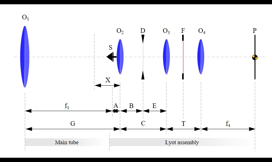
Figure 2.- Elements of SunCorGraph-I. Lenses are labled as O1 for the main lens, O2 for the field lens, and O3-O4 for the relay/telecentric lenses. Lyot stop is labled D, and the filter is F. Focal lengths of O1 and O4 are indicated as f1 and f4.
The telescope structure consists of a sequence of five Aluminum rings connected by threaded rods to form an external armour. The first ring holds the main lens, while the last ring holds a GSO Newton-type focuser (its square external support flattened so that it correctly sits on the ring). In figure 3 the external armour is depicted. In figure 4, first steps of armour construction for SunCorGraph-I, with the Lyot assembly in its first evolution (in this picture, the Newton focuser is not mounted yet, instead there are sliding ThorLabs square mounts for the SM2 tubes where the Lyot assembly is being developed, explained later).
The Lyot assembly is mounted on ThorLabs SM2 tubes with some specific adaptors, and are attached to the movable tube of the GSO focuser: one section on its front end (toward the principal lens) and the other on its rear end (toward the camera). The occulting cone (S), the lenses O2 and O3, the Lyot stop (D) and the filter (F) are located in the tube section attached to the front end of the movable focuser tube. This section can be easily detached in order to change lenses and positions of the elements. The O4 lens is located in the tube section attached to the rear end. and it can also be easily changed. A helical focuser for 1.25" eyepiece is used for supporting the camera after O4 lens. When the movable tube of the focuser moves, the whole Lyot assembly moves with it. This allows to focus the occulting cone at the principal focal plane. In figure 5, a diagram of the focuser and Lyot assembly can be seen, before mounting it into the external armour. In figure 6, a pictures of some cone mounting configuration can be seen.
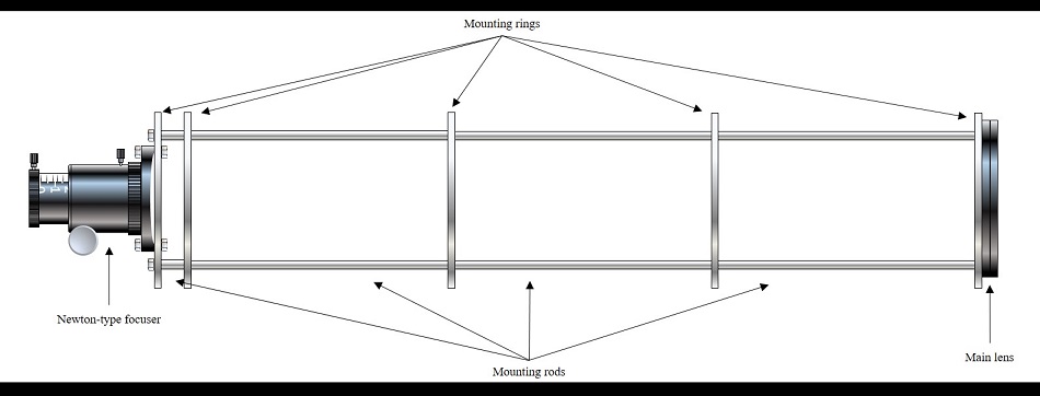
Figure 3.- External armour for SunCorGraph-I (diagram), indicating the basic elements.
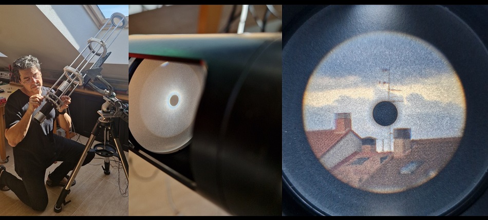
Figure 4.- (a) First steps of armour construction for SunCorGraph2. In this picture, the armour is supported on a Homemade equatorial mount made with recycled elements. The Lyot assembly seen here is not the definitive one, indeed, it is not yet provided with the GSO Newton-type focuser. (b) First tests of the Lyot assembly, with a ground glass set in the second focal plane in order to inspect the occultation of the sun. (c) Testing the image by looking to the nearby buildings.
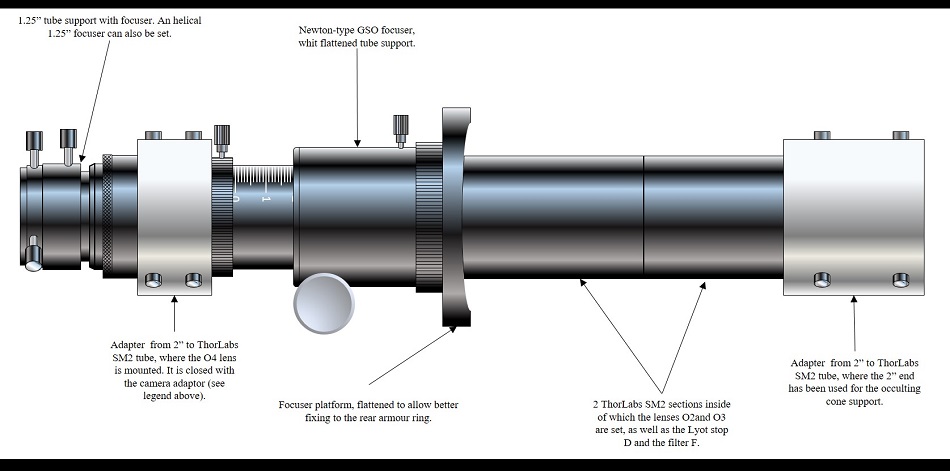
Figure 5.- Diagram of the Lyot assembly on its final evolution for SunCorGraph-I.
Figure 6 shows some details about the evolution of the occulting cone configuration. Initially, we used the classic through-the-lens clamping method. We soon realized that defects in the support system were causing bright spots and artifacts in the final image. Because of this, we redesigned the system, opting for a "floating" cone support using a radial side bar, which allowed us to use an undrilled lens.
Figure 7 shows a diagram of the Lyot assembly mounted on the external armour. A tube with internal baffles (the tube was recycled from an old laser dismantled for museum use) was used to cover the optical path from the main lens to the occulting cone. The baffles were made in the form of rings from 1 mm thick aluminum sheet, by waterjet-cut. The diameters of the rings' center holes, as well as their positions within the tube, were calculated using on purpose programmed Excel sheet. The baffles were blackened with special paint and clamped in their corresponding positions (the clamping technique is one of our best-kept secrets).
Figure 8 shows some images of SunCorGraph final assembly, as well as some of its elements.
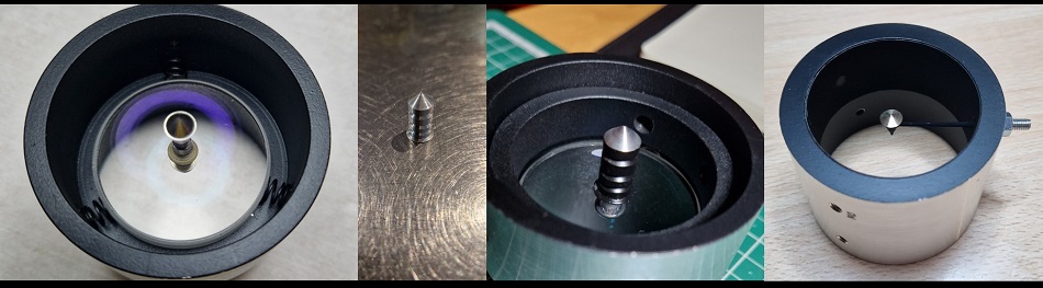
Figure 6. Some details on the evolution of the occulting cone setup. On the left, the first design based on a drill through the field lens. The drilling was successful, but small edge defects caused flare and artifacts in the final image. We redesigned the mount using a radial rod, allowing us to use an undrilled lens. This can be seen on the right. In the center, another cone design we experimented with that also failed.
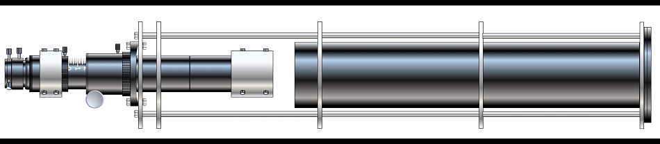
Figure 7.- Diagram of the Lyot assembly mounted on the external armour. The complete diagram of SunCorGraph-I can be seen, including the baffle tube. Note that there is a gap between the end of the baffle tube and the occulting cone support. This gap allows the cone support to be removed so that SunCorGraph can be used as a conventional solar imaging telescope. The gap facilitates heat evacuation, but at the expense of ambient light entering to the field lens laterally. In practice, the gap is covered with a black blanket which, being at some distance from the cone tube, facilitates heat evacuation.
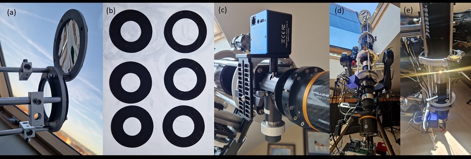
Figure 8.- Different images of the components and the final evolution of the coronagraph. (a) Close-up view of the main lens, with the rotating Mylar film that allows the telescope to be used for normal imaging or to perform preliminary focusing operations for later coronagraphy. (b) Baffles used for the main tube. (c) Focuser motor support, based on a Pegasus Cube II. (d) Global view of SunCorGraph-I, with an Apollo M Max Pro camera mounted. The equatorial fork mount supporting the telescope is a Celestron Ultima PEC from the 1980s, refurbished and with new electronics (Markarian MKee). To the left of SunCorGraph-I is a small guide telescope, which we have used to test our own guiding software. (e) SunCorGraph in action, showing the intense reflection of sunlight in the occultation cone.
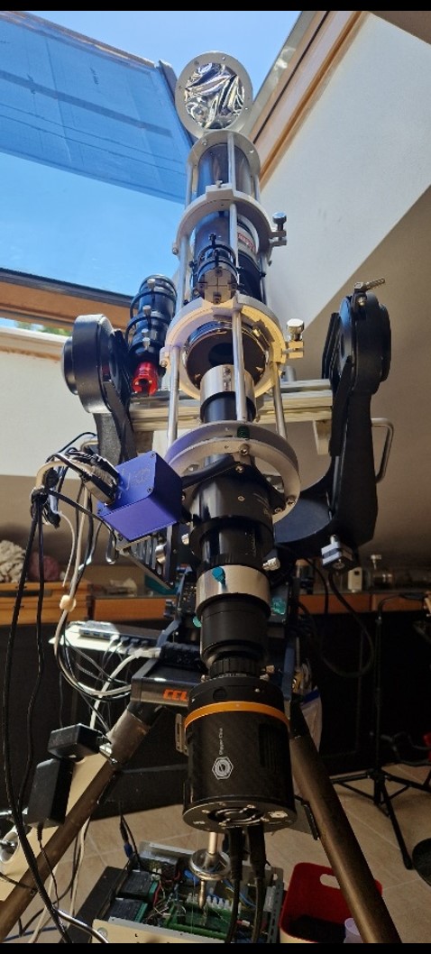
The figure 8d enlarged.
Testing SunCorGraph-I
Our design allowed us to use different Lyot configurations. The most frequently focal lengths used were (in mm) as 680-100-150 for O1, O3, O3 respectively, and 55, 40, 90 for O4. Different O4 focal lengths are used so as change image size in the sensor, without changing any of the rest elements. The main lens was a recycled achromatic doublet provided with tilting screws for alignment.
The filters used in SunCorGraph were the 7 nm bandpass Hα filter (FWHM) and the 2 nm G-Band filter. The corona was observed only once with the Hα filter, while with the G-Band, no images of the corona have been obtained so far. With the 90 mm O4 lens, the size of the sun exceeded the image frame of the ASI290MM Mini. The combination of this camera and lens with the G-Band filter provided very good images of the photosphere (shown in Figures 10 to 12).
The limited success in obtaining images of the corona is normal, as the observatory where we are located is only about 600 m above sea level. Successes are rarely reported at these altitudes. It was on February 20, 2024, when we dawned with a very clear and pure sky, with very little dispersion around the sun, that we were able to obtain the first image of the corona with SunCorGraph. This event was only repeated once more at the end of that same year. In Figure 9, the image of the corona can be seen. Configuration for this picture was 680-100-150-55, being O4 a 55 mm focal length achromatic doublet.
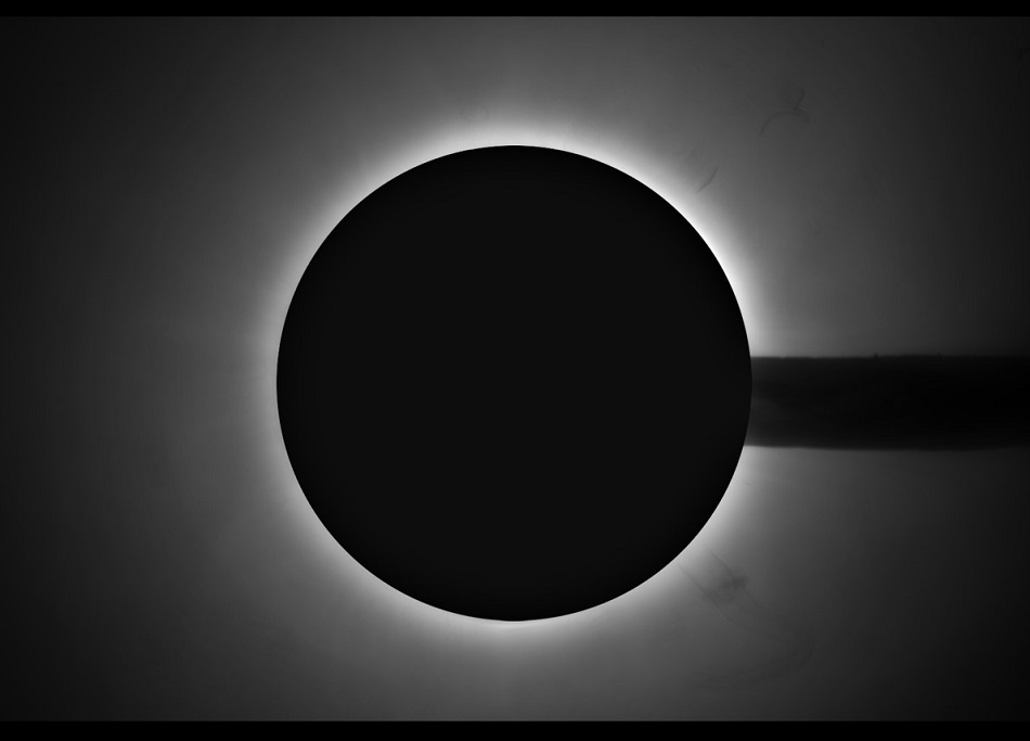
Figure 9.- The first picture of the corona taken with SunCorGraph, configured as 680-100-150-55, with Ha filter (7 nm bandpass). Captured with ASI290MMMini. Some dust appears on the right, coming from the 55 lens.
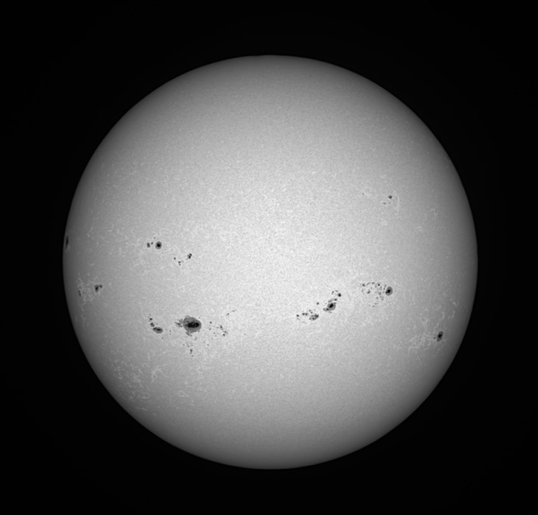
Figure 10.- Picture taken during 2024 summer, with configuration 680-100-150-90, ASI29MM Mini, G-Band 2nm and Mylar blocking filter.
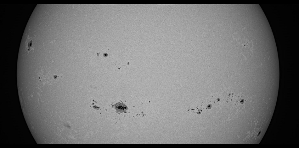
Figure 11.- Picture taken during 2024 summer, with configuration 680-100-150-90, ASI29MM Mini, G-Band 2nm and Mylar blocking filter. The largest spot shows bridges.
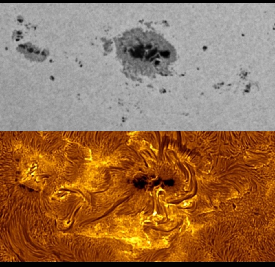
Figure 12.- The main spot of picture 11 is shown here enlarged (top) in comparison with the same spot taken with 150 mm aperture telescope with narrow band (0.3 A) Hα filter (bottom).